


- 1
- 2
- 3
- 4
- ���F�ڵ�λ�ã� ��EDA�W >> CST >> CST�OӋ���� >> ����
CSTͬ�S�������ķ����OӋ������CST2013�OӋ����
Model the Inner Conductor
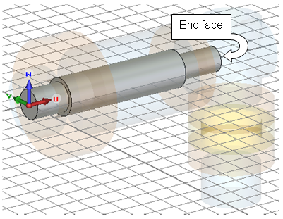
Creation of the inner conductor of the coaxial cable can again be simplified by aligning the working coordinate system with the front face shown in the above picture:
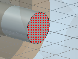
1. Activate the pick face tool (Modeling: Picks > Picks > Pick Point, Edge or Face (S) )
2. Double-click on the front face shown above.
3. Align the WCS with the picked face (Modeling: WCS > Align WCS )
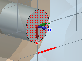
The new location of the working coordinate system should then be shown as pictured below:
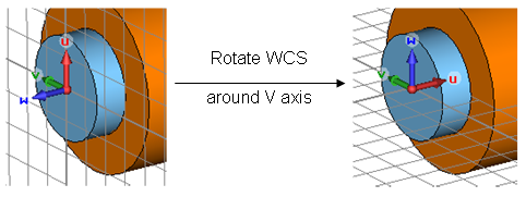
Next, the WCS should be rotated such that its u axis points into the structure by invoking the command Modeling: WCS > Transform WCS and define Rotate +90�� around V axis (Shift+v).
Now the first part of the inner conductor can be modeled by a figure of rotation that is shown in the schematic drawing below:
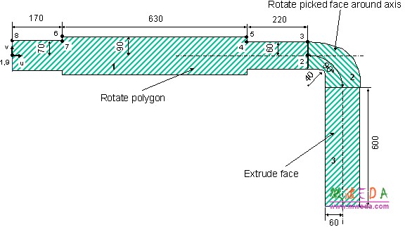
Since the construction of a figure of rotation has already been explained in detail earlier in this tutorial, we will only give a short list of steps:
1. Activate the wire frame visualization mode by pressing View: Visibility > Wire Frame or using the shortcut Ctrl+w. This will allow you to follow the construction; otherwise, the parts of the inner conductor will be hidden inside the previously created shapes.
2. Activate the figure of rotation tool (Modeling: Shapes > Extrusions > Rotate .)
3. Enter the points shown in the table below by pressing the Tab key and specifying the coordinate values numerically:
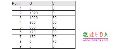
4. Once the last point has been defined the polygon is closed. The rotate profile creation dialog box will open. In this dialog box check the points coordinates, set the Name of the shape to conductor1 and change the Material assignment to PEC before pressing OK.
After successfully performing these steps, the structure should look as follows:
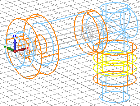
Please select the inner conductor by either double-clicking on it in the view or by selecting component1 conductor1 from the navigation tree. Once this is done, you may deactivate the wire frame plot mode (View: Visibility > Wire Frame or Ctrl+w):
The next step is to align the working coordinate system with the inner conductors end face shown above. Therefore, rotate the view to ensure that the end face is visible (select View: Mouse Control > Rotate and drag the mouse while pressing the left button). Afterwards, activate the general pick tools (Modeling: Picks > Picks > Pick Point, Edge or Face (S)) and double-click on the desired face.
Now, align the WCS with this face by pressing Modeling: WCS > Align WCS or shortcut w. The next step is to define a rotation axis by selecting Modeling: Picks > Picks Edge from Coordinates . Enter the first points coordinates by pressing the Tab key (U = 100, V = 0) and the coordinates of the second point (U = 100, V = 100) in the same manner. Finally, check and confirm the settings in the dialog box.
-
CST����ҕ�l�̳̣��Y����v�⣬ҕ�l������ʾ���Ļ��A�v��ѭ��u�M�����Y�����¹��̰������������ٌW������CST���OӋ����...��Ԕ����B��
- CST�쾀�OӋ���쾀��OӋ��CST2013�OӋ����
CST�C��ǻ�w�OӋ������CST2013�OӋ����
ʹ��CST���������M��TDRӋ�����
CST�cMatlab�B���O��
CST�������Һ�Agilent ADS �fͬ�����B���O��
CST�������Ҳ鿴VSWR�Y��
CST��������Y������c�ⲿ�����M�б��^
CST�������Ҳ��õ���Ҫ�㷨
ʹ��CST�������ҵĕr�����������늴��}��
늴ż��ݵĔ�ֵ�����������CST2013
CST�������ܺͷ��漼�g
CST�OӋ�h�� �� CST2013
���]�n��

-

7������ҕ�l�̳�,2���̲�,�Әӽ���
-

����������������ADS��Ӗ�̳����b
-

��ȫ��������l�����OӋ��Ӗ�ϼ�
-

Ansoft Designer �W����Ӗ�n�����b
����Ansoft Designer������Ӗ�̲�
-
ʸ�W,�l�V�x,��̖Դ...,�ӘӾ�ͨ
-

�c�I���B�Ӿo�ܵ��n��,�W������...
-

�I���ţLes Besser����Ӗ�n��...
-

Allegro,PADS,PCB�OӋ,�䌍�ܺ���..
-

Hyperlynx,SIwave,�����QSI���}
-

�F���v��,���r����,�����W���ɲ��`